3: Three components
Adding another component to the series or parallel combination discussed in part 2 yields one of four possible networks, which I've labelled (a) - (d) so that we'll all know which one I'm talking about. It's not difficult to find the impedance of each network. The trick is to express it in a way that shows immediately how the network will behave, in terms of up-breaks and down-breaks in the impedance, like this:
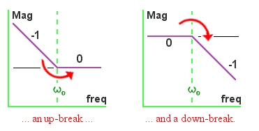
As I mentioned in Chapter 2, the up-breaks (where the impedance graph abruptly rotates upwards, or anti-clockwise) happen when a term like [1 + jω/ω0] appears on the TOP of the impedance expression, and the down-breaks (where the graph starts to head downwards, or rotates clockwise) happen when a similar term appears on the BOTTOM. The break happens at the frequency ω0.
Two resistors, and one capacitor . . .
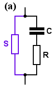
Network (a) consists of . . . the new resistor S, in parallel with ZS (from Chapter 1), or in symbols,
Za = S [ 1 + jω/ω0 ] / [ 1 + jωC (R + S) ] . . . . . where ω0 = 1/ (CR), as before.
Now, if 1/ (CR) is the break frequency ω0, then 1/ C(R+S) is evidently another break frequency. It's appeared in network (a), so I'll call it ωa. So I can write the impedance as
Za = S [ 1 + jω/ω0 ] / [ 1 + jω/ωa ]
This expression has (1 + jω/ω0) on the top, and (1 + jω/ωa) on the bottom, which means that the impedance will begin to rise at ω0 (an up-break) and at some other frequency ωa it will begin to fall (a down-break).
Which will happen first? That's easy: {C(R+S)} must be bigger than {CR}, so ωa must be smaller than ω0. The down-break will happen at a lower frequency than the up-break. The impedance will be constant at low frequencies, then begin to fall, then level off again.
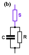
Network (b) consists of . . . the new resistor S, in series with ZP (from Chapter 1), or in symbols,
Zb = (R + S) [ 1 + jωC {RS/(R + S)} ] / [ 1 + jω/ω0 ] . . . . . where ω0 = 1/ (CR), as before.
Again, 1/ C {RS/(R+S)} is evidently a break frequency: I'll call this one ωb. And since {RS/(R+S)} (that is, R in parallel with S) must be smaller than either R or S, then ωb must be larger than ω0.
This network has an up-break at ωb (because the ωb term is on the top) and a down-break at ω0 (with the ω0 term on the bottom), so for this network too, the down-break will happen at a lower frequency than the up-break.
I find it useful to check the algebra with a little common sense, too. Just looking at these two networks, it's clear that at dc (when the capacitor is an open-circuit) they will both look like a resistor, and at the speed of light (when the capacitor is a short-circuit) they will both look like a smaller resistor. The impedance of network (a) will fall from S at dc to [R-in-parallel-with-S] at light-speed. The impedance of network (b) will fall from [R+S] at dc to just S at light-speed. Of course the the down-break will happen at a lower frequency than the up-break.
Straight-line approximations for networks (a) and (b)


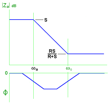
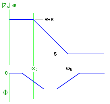
Examples: Suppose that R=330Ω and C=470nF, as they were in Chapter 2, making f0 (= ω0/2π) = 1.03 kHz, and that S is a 3.3kΩ resistor. What will these two networks do?
"rps" means, radians per second
In network (a) the new break frequency is ωa = 1/ C(R+S) = 586 rps, so fa = 93 Hz. |Z| will be 3300Ω at low frequencies; it will begin to decrease above 93 Hz; and it will level off towards 300Ω at frequencies above 1.03 kHz.
In network (b) the new break frequency is ωb = 1/ C {RS/(R+S)} = 7090 rps, so fb = 1.13 kHz. |Z| will be 3.63kΩ at low frequencies; it will begin to decrease above 1.03 kHz; and it will level off towards 3.3kΩ at frequencies above 1.13 kHz. (In other words, the series 3.3kΩ resistor will pretty much swamp everything else).
I have deliberately not shown a scale on the phase graphs, because although the phase moves away from zero between the break frequencies, how far it moves depends on the break frequencies. If they are very far apart, the phase shift will get close to -90°. If they are close together, it may be only a few degrees.
One resistor, and two capacitors . . .
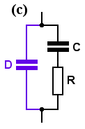
Network (c) consists of . . . the new capacitor D, in parallel with ZS (from Chapter 1), or in symbols, the impedance is
Zc = [ 1 + jω/ω0 ] / jω (C+D) [ 1 + jω {R CD/(C+D)} ]
As before, 1/ R {CD/(C+D)} is evidently a break frequency (because 1/ [Resistance*Capacitance] is ALWAYS a break frequency), and I'll call this one ωc. Then the impedance can be written more simply as
Zc = [ 1 + jω/ω0 ] / jω (C+D) [ 1 + jω/ωc ] . . . . . where ω0 = 1/ (CR), as before.
This expression has an up-break at ω0, and a down-break at ωc. It also has an over-riding down-slope due to the (jω) term on the bottom, just like a simple series CR network. At dc, the capacitors block any current and the impedance is infinite. The impedance begins to fall as the frequency rises and the capacitors grudgingly allow more and more current to flow through them. And because CD/(C+D) is always smaller than either C or D, it follows that ωc is always larger than ω0, so in this network the up-break will happen at a lower frequency than the down-break. If you hadn't noticed, this is the opposite of what happens in networks (a) and (b). So the impedance graph will slope down at low frequencies, then level off, then slope down again.
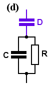
Network (d) consists of . . . the new capacitor D, in series with ZP (from Chapter 1), or in symbols, the impedance is
Zd = [ 1 + jωR (C+D) ] / jωD [ 1 + jω/ω0 ] . . . . . where ω0 = 1/ (CR), as before.
This time the up-break happens at the new break frequency of 1/ R(C+D), and I'll call this ωd, allowing the impedance expression to be written as
Zd = [ 1 + jω/ωd ] / jωD [ 1 + jω/ω0 ]
So this expression has an up-break at ωd, and a down-break at ω0. It also has an over-riding down-slope due to the (jω) term on the bottom, just like a simple series CR network, and just like network (c). And since R(C+D) is always larger than RC, ωd is always smaller than ω0. The impedance graph will slope down at low frequencies, then level off, then slope down again, just like network (c).
Straight-line approximations for networks (c) and (d)


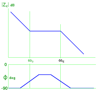
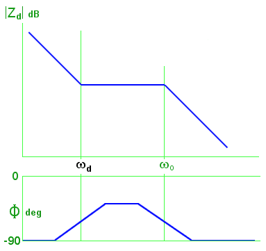
Examples: Suppose that R=330Ω and C=470nF, as they were in Chapter 2, making f0 (that is, ω0/2π) = 1.03 kHz, and that D is a 47nF capacitor. What will these two networks do?
In network (c) the new break frequency is ωc = 1/ R {CD/(C+D)} = 70.9 krps, so fc = 11.3 kHz. At low frequencies, |Z| will fall steadily as frequency rises; between 1.03 kHz and 11.3 kHz |Z| will tend to be constant; at higher frequencies |Z| will fall steadily as frequency rises.
In network (d) the new break frequency is ωd = 1/ R(C+D) = 5.86 krps, so fd = 933 Hz. At low frequencies, |Z| will fall steadily as frequency rises; between 933 Hz and 1.03 kHz |Z| will tend to be constant; at higher frequencies |Z| will fall steadily as frequency rises. (In other words, it will behave pretty much like a 47nF capacitor!)
For these networks the phase moves away from -90° back towards zero, but again, how far it gets depends on the ratio between the break frequencies. If they are close together, the phase-shift doesn't change much.
The impedance at mid-band - where |Z| is (almost) constant - can be found from the Z equations by assuming a frequency well above the lower break-frequency but much smaller than the upper break-frequency, so that the [ 1 + jω/ωx ] terms can be approximated (by neglecting one term or the other) to simplify the algebra. (Of course, if the two frequencies are close together, |Z| is never going to be constant, and these |Z| results will be more or less approximate).
For (c), this impedance is: . . . . . . . . . |Zc| = R [C /(C+D)] . . . . . in the Example, |Zc| = 300Ω
and for (d), it is: . . . . . . . . . . . . . . . . |Zd| = R [1 + (C/D)] . . . . . in the Example, |Zd| = 3.63 kΩ
Designing a real network like (a) or (b)
The equations show how the networks will behave, but designing a real network involves calculating the component values needed to get a particular response shape. The design will specify what the network should do - that is, what its impedance magnitude should be (|ZL| at low frequencies; |ZH| at high frequencies), and where its break frequencies (ωL & ωH) should be. We need equations that express C, R and S in terms of these four parameters.
Isn't this impossible, though? How can you solve a problem having four specified constraints (the two |Z|'s and the two ω's) with only three variables (C, R and S). Don't three variables allow only three constraints?
The answer is, yes, but the network has only three constraints, because |Z| slopes downwards at 20 dB/decade between the two break frequencies. If (say) |ZL|, ωL, and ωH are fixed, then |ZH| is also fixed. It depends on |ZL| and on the ratio between the break frequencies. |ZH| will be whatever these three parameters force it to be. You can't choose it to be something different. Ye cannot change the laws of physics, as they say on Star Trek. I've ignored |ZH| in deriving the expressions for C, R & S (below), which may mean that they are not quite in the form you need to solve a particular problem. A little algebra may be necessary before you can apply them. Life's often like that.
Network (a) is designed like this:

C = (ωH - ωL) / ZL ωL ωH
R = |ZL| ωL / (ωH - ωL)
S = |ZL|
Network (b) is designed like this:

C = ωH / |ZL| ωL (ωH - ωL)
R = |ZL| (ωH - ωL) / ωH
S = |ZL| ωL / ωH
Since these two networks do the same job, it's worth asking whether one might be cheaper to build than the other - and it turns out that the capacitor in (a) is always smaller than the one in (b). Smaller often means cheaper, so (a) ought to be the designer's first choice.
A real-life design example

BT say (in SIN 351) that the impedance of a UK telephone line can be approximated by this network. Could it be built more cheaply?
The break frequencies of this network are 828 Hz and 2.22 kHz, and its resistance at dc is obviously 990Ω.

So in its alternative form, the component values will be as I show here. Would this network be cheaper? The capacitor is smaller in this version, but the unusual resistor values could be troublesome.
If I was betting real money on the outcome, I would use a simulator to plot the behaviour of BT's model, and then see whether I could get the behaviour of the alternative to be good enough using only preferred-value components.
Designing a real network like (c) or (d)
These networks have three constraints: the two break frequencies, and the mid-band region between them where the impedance - I'll call it |Zmid| - is reasonably constant.
Network (c) is designed like this:
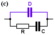
C = (ωH - ωL) / |Zmid| ωL ωH
D = 1 / |Zmid| ωH
R = |Zmid| ωH / (ωH - ωL)
Network (d) is designed like this:

C = 1 / |Zmid| (ωH - ωL)
D = 1 / |Zmid| ωL
R = |Zmid| (ωH - ωL) / ωH
Looking at these two, it's apparent that the capacitors in (c) are effectively in parallel, whilst those in (d) are effectively in series. One might expect that network (c) would require smaller capacitors, and so be cheaper to make. Let's see.
A design example
Suppose we wanted to design a network (as part of an active filter, say) to correct for the BT telephone line break frequencies of 828 Hz and 2.22 kHz, with a mid-band impedance of 10 kΩ.
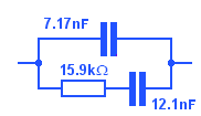

The capacitor values seem much the same. Either network would do. I'd still find out what difference preferred-value components would make to the response, though.
... Part 4: Second-order networks ...
