
This page is about how to keep transistors cool, and why it matters that you do. The same arguments apply if you're trying to prevent a microprocessor from running so hot it glows in the dark.
Power dissipation
All electronic components dissipate heat. In most cases the amount of heat generated is negligibly small, but when a device is carrying a current of more than 100mA or so it may get warm. This includes capacitors, by the way. The electrolytic capacitors in a switched-mode converter can be carrying huge currents, which is why it matters that they have very low intrinsic resistance. I've known electrolytics explode.
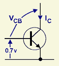
Here is a transistor carrying a collector current of IC at a collector-base voltage of VCB. Suppose it's a low-level amplifier, with IC = 2mA and VCB = 5v. It's dissipating a power of IC x VCB = 10mW, which is not worth worrying about. But suppose it's an output transistor in an audio amplifier, where VCB = 50v and the average IC is 1 amp. Now the device has to get rid of 50 watts of heat, and that definitely is something to worry about. The transistor will need help to move the heat safely away.
Power transistors
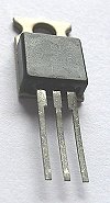
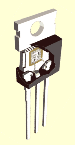
Almost all the power is dissipated at the base-collector junction, deep inside the transistor. The cutaway drawing of a TO-220 power transistor on the left shows a tiny chip stuck onto the block of metal that forms the main body of the device. The metal tab acts as a built-in heatsink. This sketch shows what's inside the chip itself.
The earlier package style of TO-3 (above, right) used the same idea. The chip is stuck firmly onto the largest available piece of metal, which is therefore electrically connected to the transistor's collector, as it is for the TO-220 device and indeed for most power transistors.
It can be interesting to saw the lid off a component and see what's underneath. I'd always assumed that a power transistor chip was much bigger than it actually is.
Heat flow
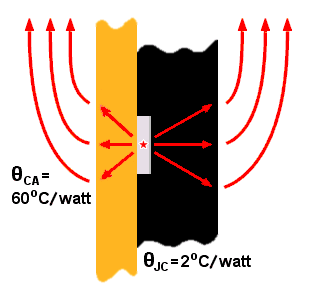
The heat appearing at the base-collector junction moves through the collector tab and warms up the surrounding air. How quickly it moves depends on the quality of the thermal contact between the two surfaces.
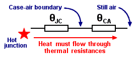
Heat flow calculations can be very difficult and time-consuming, so somebody had the bright idea of a writing a sort of thermal Ohm's Law. Voltage translates into temperature difference, and current into power flow. Resistance then maps to "thermal resistance", measured in degrees C per watt. Since the designer knows how much power is involved, and the transistor manufacturing company publishes the thermal resistances of their devices, calculating the temperature differences is easy.
Example
Suppose the transistor shown above is dissipating 2 watts into still air at 25oC. How hot is the junction?
The temperature difference between the junction and the case is 2w x 2oC/w = 4oC. So the case is 4oC hotter than the junction.
But the case is running at 2w x 60oC/w = 120oC hotter than the surrounding air, which is itself at 25oC. So the junction temperature will be
TJ = 25o + 120o + 4o = 149oC.
That's really too hot for the designer to feel comfortable. The transistor should have some form of heatsink, even though it's dissipating a modest 2 watts.
Heatsinks

100mm wide
x 150mm high delivers 0.95oC/watt
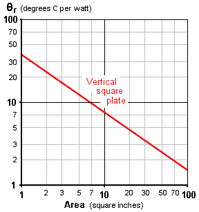
A heatsink is a metal plate. Its function is to provide an easy path for the heat generated in the transistor to reach the surrounding air. The whole heatsink is at more or less the same temperature, because heat propagates through metal much faster than through air, so an efficient heatsink needs a large surface area. A black vertical plate is one solution. Adding fins makes the heatsink more compact and easier to fit into the finished system.
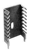
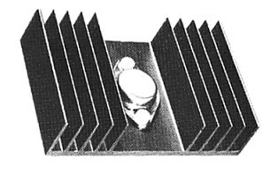
The TO-220 heatsink above (left) offers 13oC/watt, whilst the larger TO-3 heatsink manages 1.9oC/watt. The most efficient heatsinks I know of can get down to 0.3oC/watt, but if the problem is as serious as that I'd be looking at fan cooling.
The transistor can be bolted directly onto the heatsink, but there are two problems with this. First, it means that the heatsink is at the same voltage as the transistor collector, so the whole structure may have to be insulated. Second, there's a thermal resistance where the two metal surfaces touch, and it could be as high as 5 degC/watt. The first problem can be solved by fitting a thin mica washer to insulate the transistor from the heatsink (which only adds about 0.5 degC/watt to the thermal resistance), and a special plastic bush to insulate the mounting bolt. The second is usually fixed by adding a smear of silicone grease (or a proprietary compound containing suspended metal particles) between the surfaces. Silicone grease is a better conductor of heat than air.
Reliability

early heatsink
... primitive,
but very reliable
Semiconductor devices stop working for a variety of reasons, but most failure mechanisms do seem to have one factor in common - the hotter the device runs, the sooner it will fail. Semiconductor manufacturers routinely test their products at high temperatures to accelerate the onset of failures. The high-temperature failure rate can then be used to assess the likelihood of failure at a more normal temperature from the Arrhenius equation:
![]() . . . so running a semiconductor 10oC cooler could double its life.
. . . so running a semiconductor 10oC cooler could double its life.
where (if you care) AFt is the acceleration factor due to temperature, Ea is the activation energy (eV), k is Boltzmann's constant, and Tu and Ta (oK) are the temperatures in normal use and in the accelerated test, respectively. The point is, cooler devices survive longer.
Design
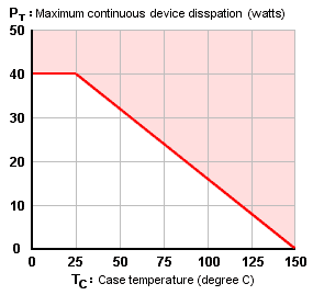
The designer must ask: How hot do I want the junction to run?, and then
How big a heatsink will I need to get down to the temperature I want?
Semiconductor manufacturers publish graphs like this one on the right. It shows that the transistor can dissipate 40 watts - but only if its case can be kept at room temperature or below. A moment's thought shows how difficult this would be in practice. The transistor will be mounted on a board inside an enclosure, with the air around it being heated by all the other components in the system. And even if the cooling problem could be solved, the transistor's junction would still be running at its absolute maximum specified temperature of 150 degrees C. I wonder how long it would survive. Months? Weeks? If I needed a transistor to disspate 40 watts, I wouldn't choose this one.
In the end it comes down to rules of thumb. Some say that no component should have a surface temperature higher than 90 degrees C. I usually aim for a junction temperature of below 100 degC (which is much the same thing). There's no special reason for this - it just feels right. Heatsinks aren't expensive, and predicting reliability is a rather uncertain business. It's better to err on the side of caution.
Example

Suppose the transistor in the previous example must dissipate 10 watts into still air at 30oC. How big a heatsink would be needed to keep its junction temperature below 100oC?
The temperature difference between the hot junction and the transistor's case (that is, the mounting tab) will be 2 x 10w = 20oC. So if the junction is at 100oC, the case will be at 80oC. So the heatsink must move 10w across a temperature difference of (80o - 30o) = 50oC.
The heatsink's thermal resistance must then be no more than (50oC / 10w) = 5oC/watt.
The designer simply looks through the catalogues for a suitable heatsink of convenient size and shape. If it turns out there isn't one - if the only suitable heatsink is specified at (say) 6oC/watt - then the junction would have to run slightly hotter.
The case temperature would be (30o + 6 x 10w) = 90oC, so the junction would run at (90o + 20o) = 110oC, but that should make no practical difference.
It's worth mentioning that small transistors can get hot, too. The TO-92 package (left) has a thermal resistance of around 350oC/watt, case to junction. Most TO-92 transistors are rated at 360mW maximum. So if this little transistor is trying to dissipate 200mW (say) into air at 30oC, its junction will be running at a surprising 100oC!


